Mood Board
Here’s how I’m feeling about brains this week.
Does Brain Size Matter?!
Carboard 3D Prototype
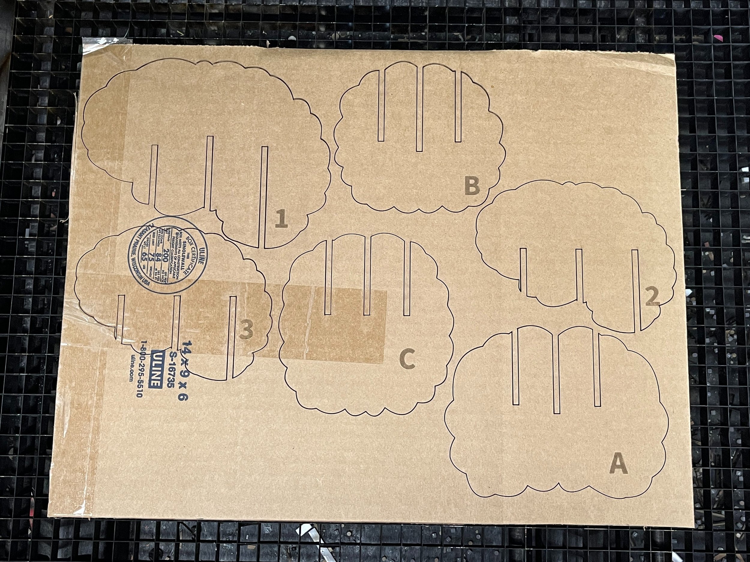
So if you’re following along with my brain journey you know that last week I was trying to slice up a 3D model of brain to make up my sculpture. You also know that I had a lot of Fusion confusion and couldn’t figure it out. So I gave up and decided to go free hand in Illustrator. Basically I copied the shapes I drew for my circuit prototypes and shrunk them down for the outer cross sections. I added in the slots so that the pieces could fit together.
Laser cutting!
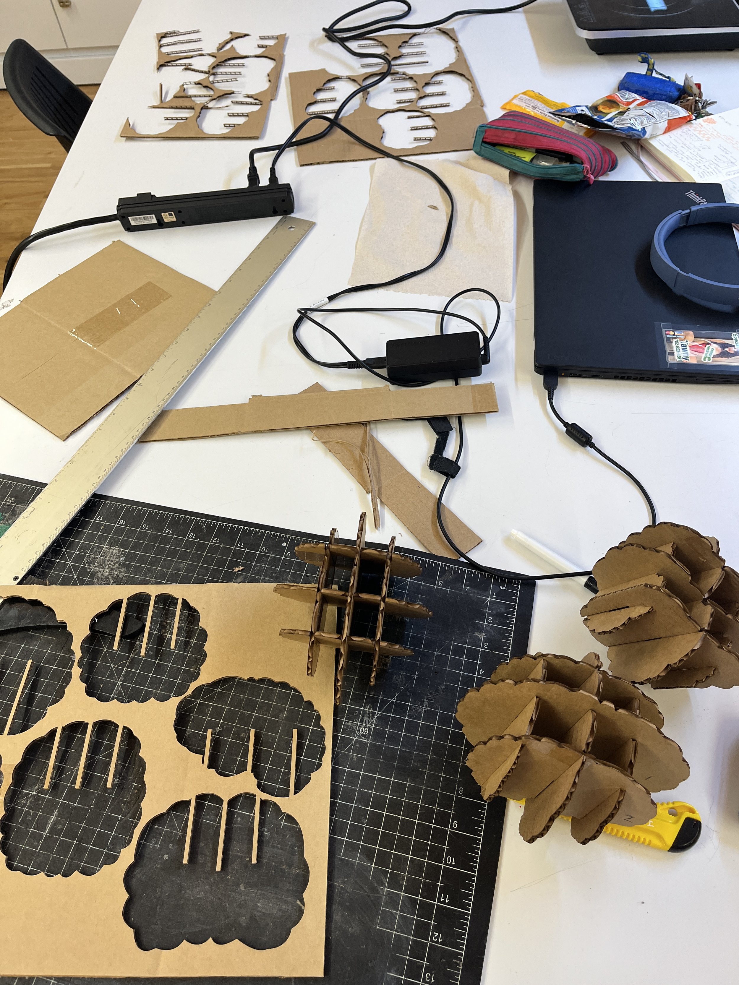
Here’s my mess
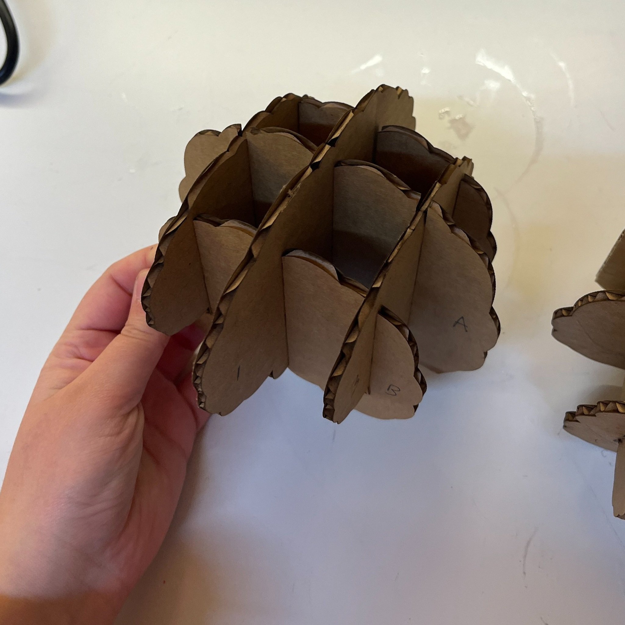
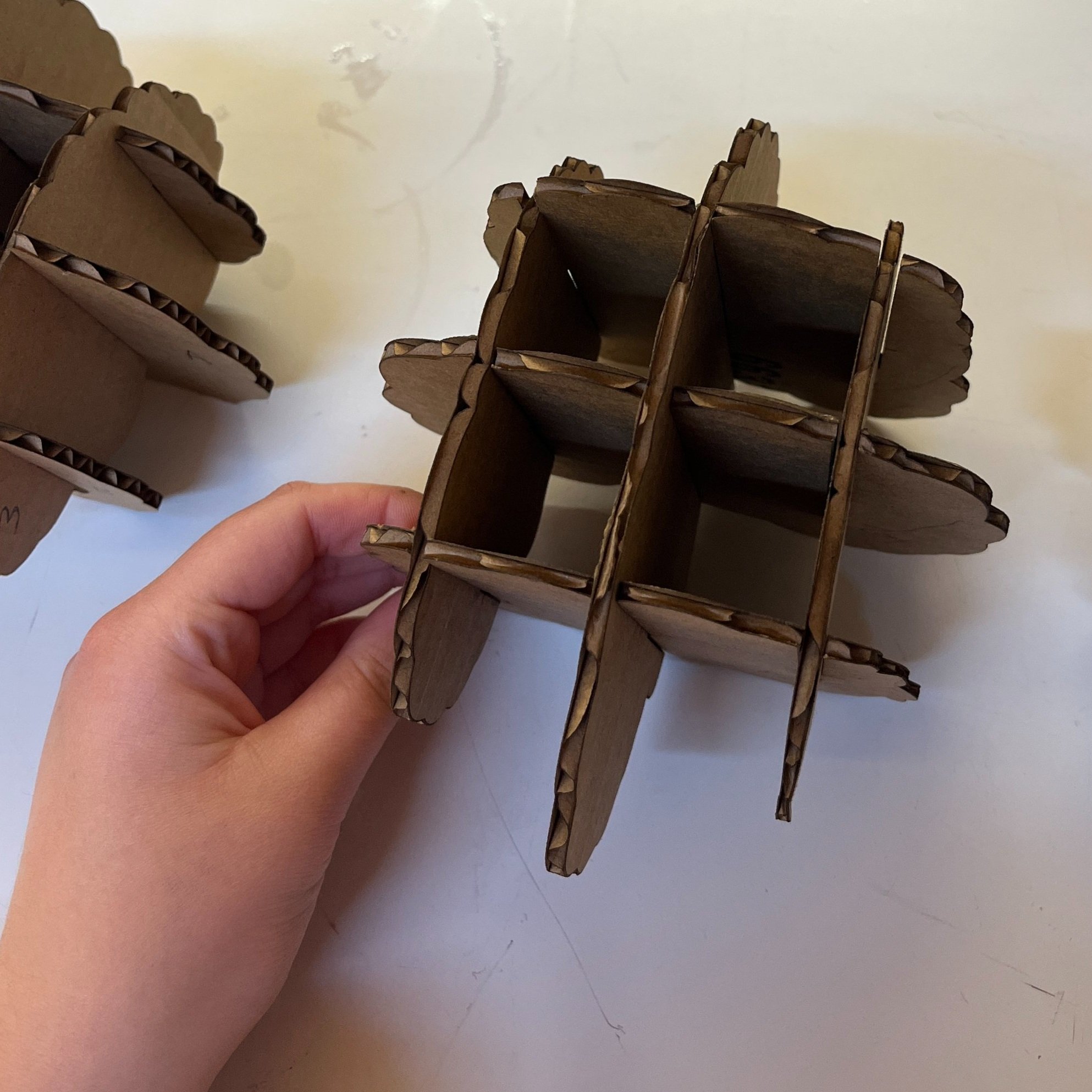
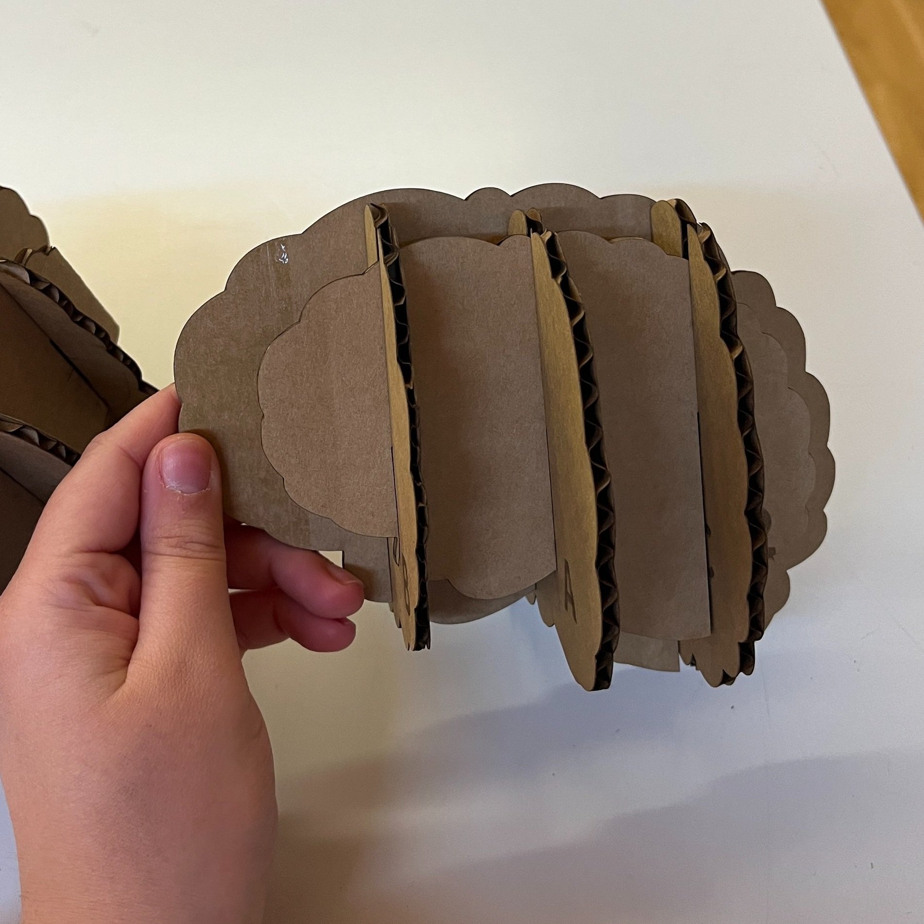
I basically repeated this process, adjusting all the cross sections drawings, until I was happy with the overall shape. It took me three iterations of cardboard prototypes to get the shape just right. The one I landed on for my sculpture is the right side.
Proto 1
Proto 2
Proto 3 - Winner!
Bioplastic
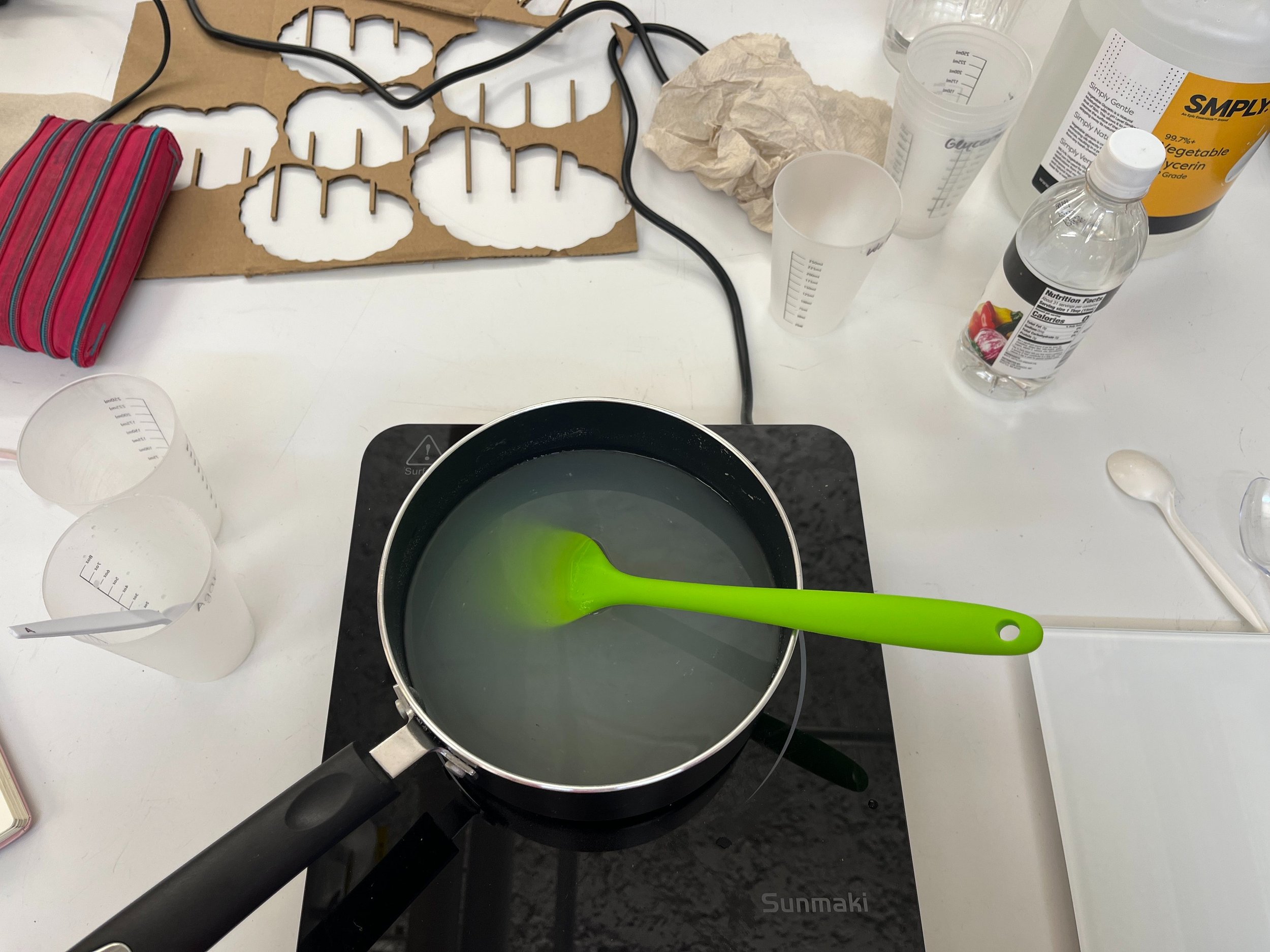
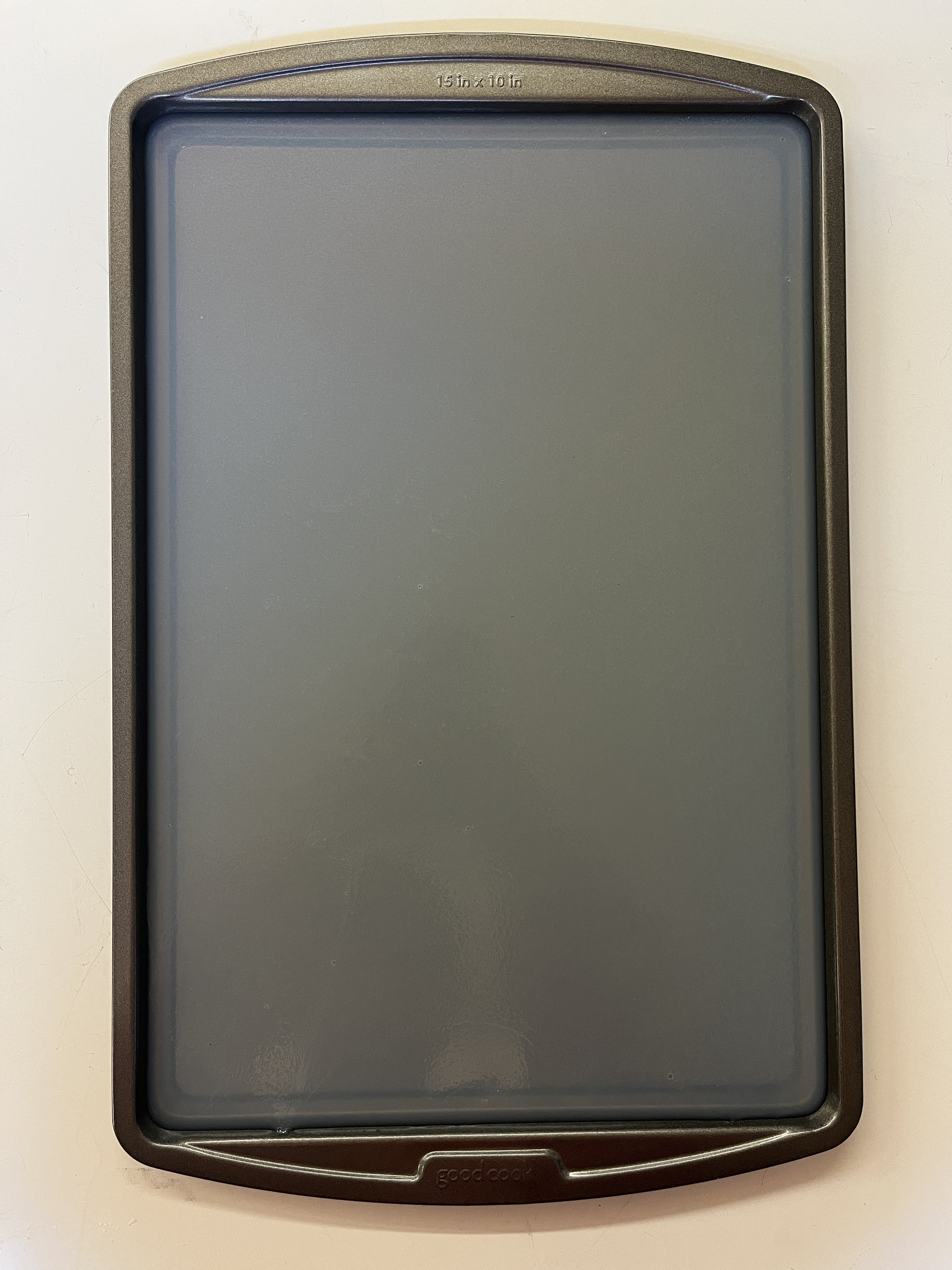
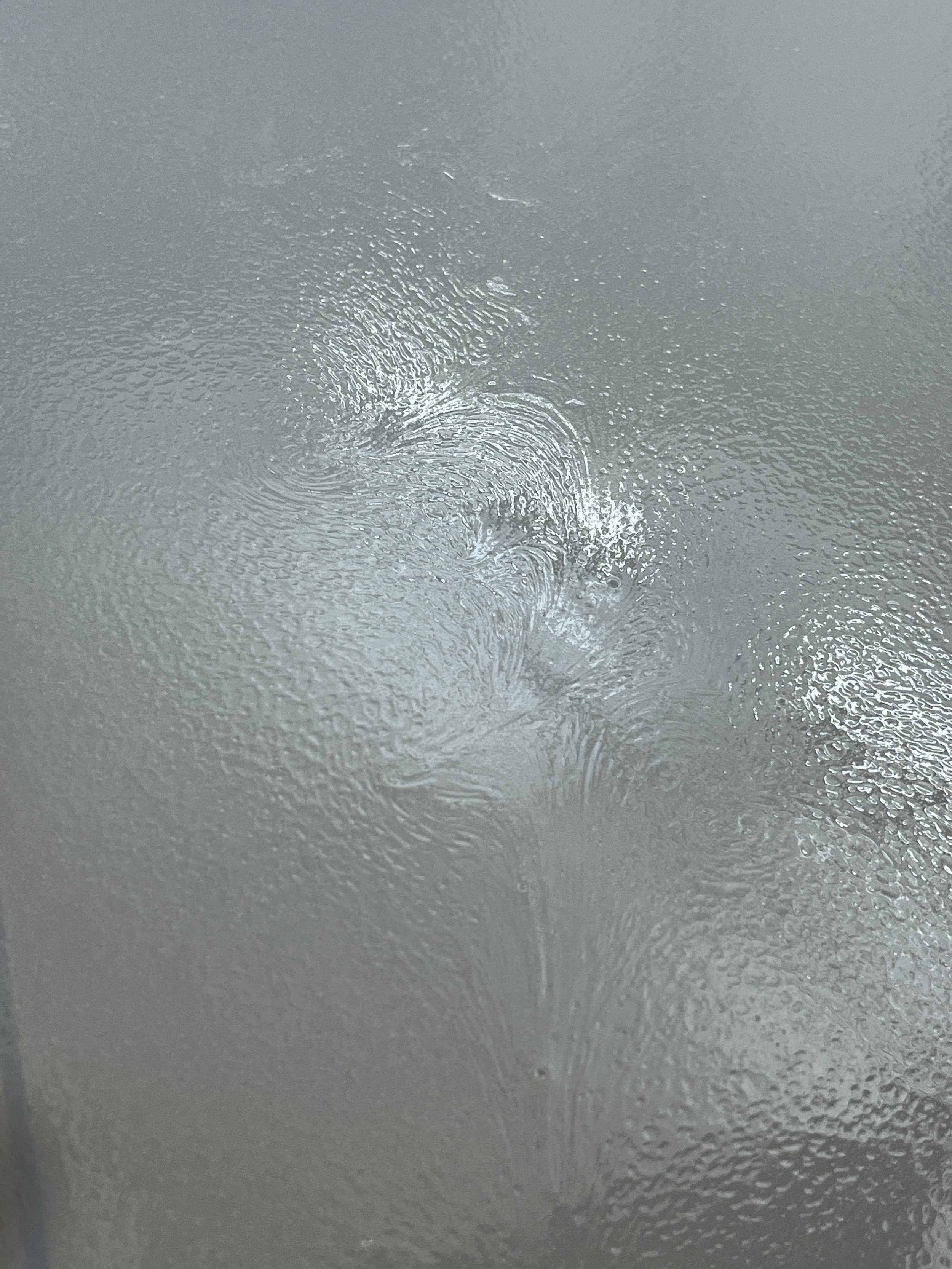
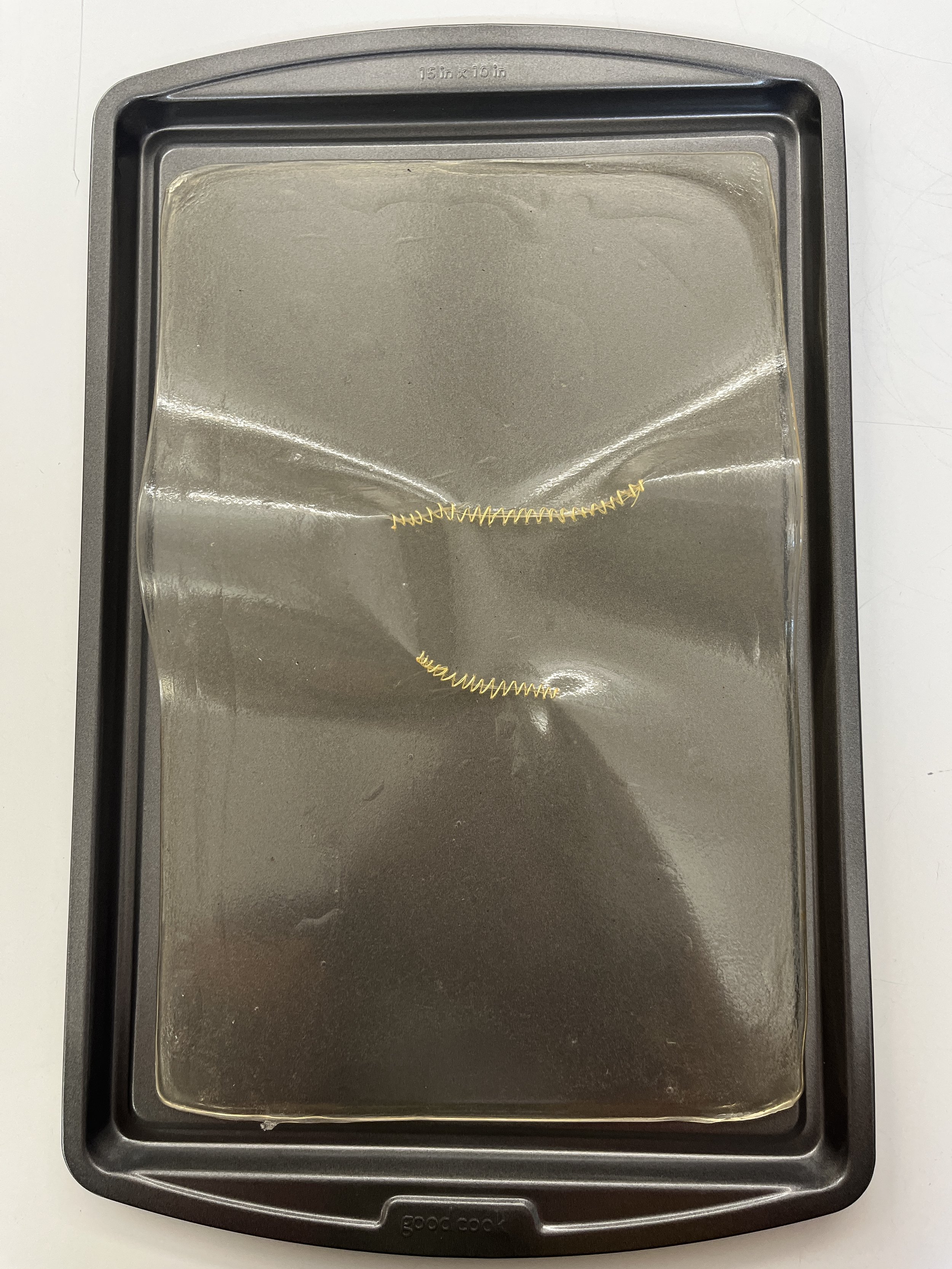
I have been really curious about how I could add my bioplastic research to my art practice. Selfishly I also think adding a bioplastic component to my work would add a unique component to my sculpture and be a great contrast to the sterile/cold/technological feel of the circuit boards. Here’s the most beautiful preemptive agar agar bioplastic I cooked on 11/19/23 for unspecified future use.
RECIPE
Water = 800mL, glycerin = 60g, agar = 39g, 1/2 cap of vinegar
COOKING SEQUENCE
140 degrees for 5 minutes, 176 degrees for 7 minutes, 212 degrees for 7 minutes, 248 degrees for 7 minutes, 212 degrees for 7 minutes
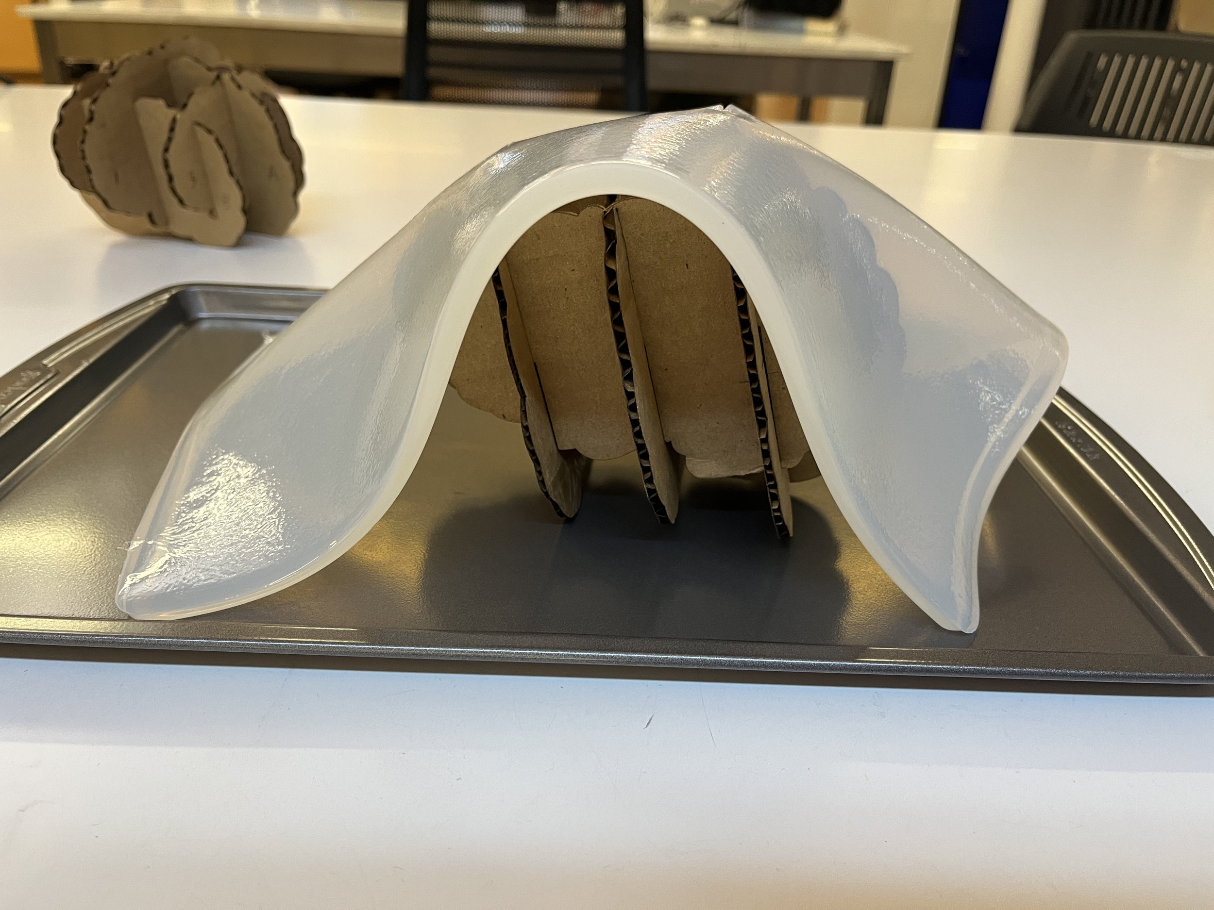
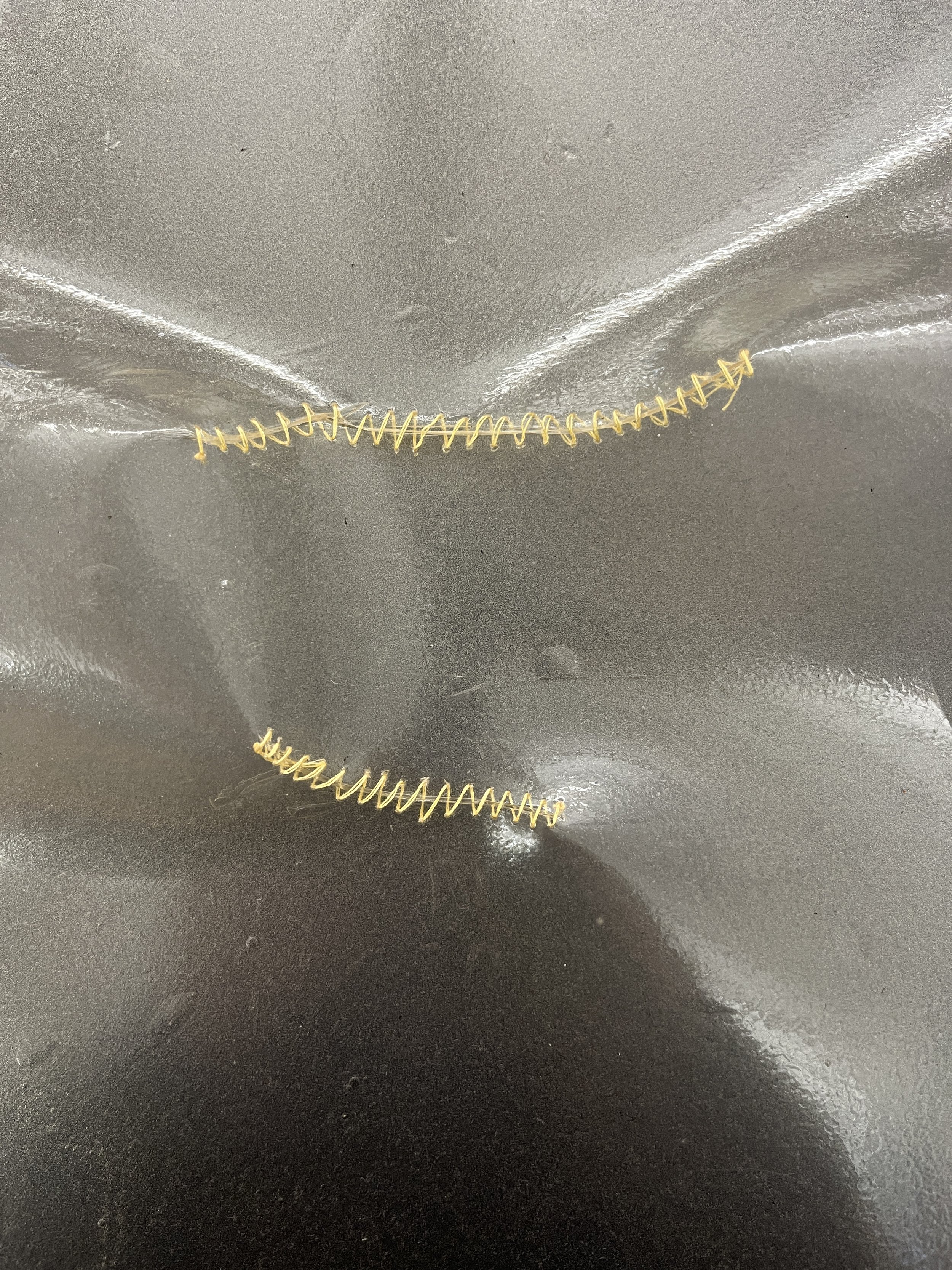
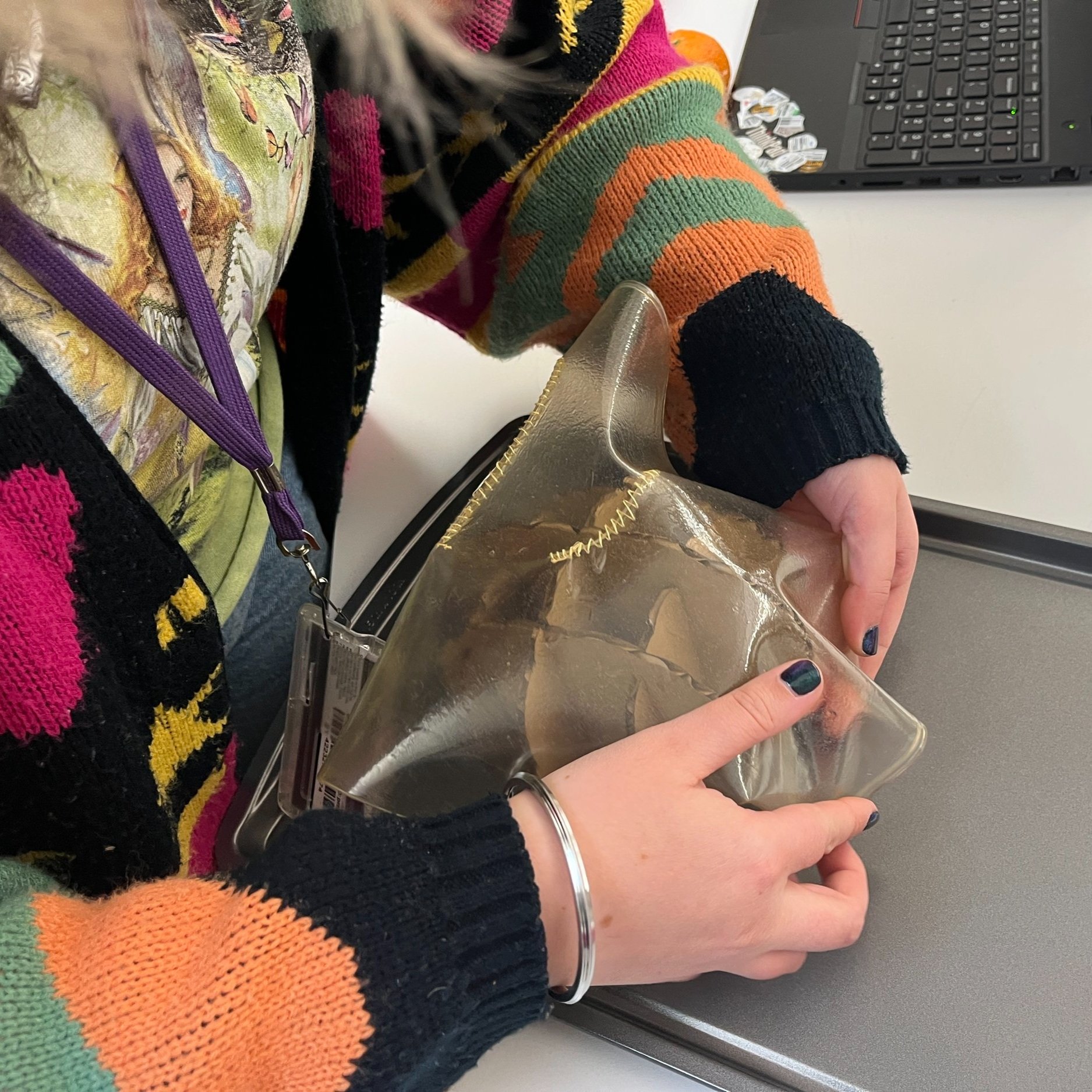
I’m also trying to practice embodied making so I’m kind of going into this one without a plan. This is a picture from the next day (11/20) trying to drape the bioplastic around the brain prototype. I thought it might dry and conform to the shape of the cardboard but I should’ve known that the plastic was still to moist and heavy. It ended up ripping at the top.
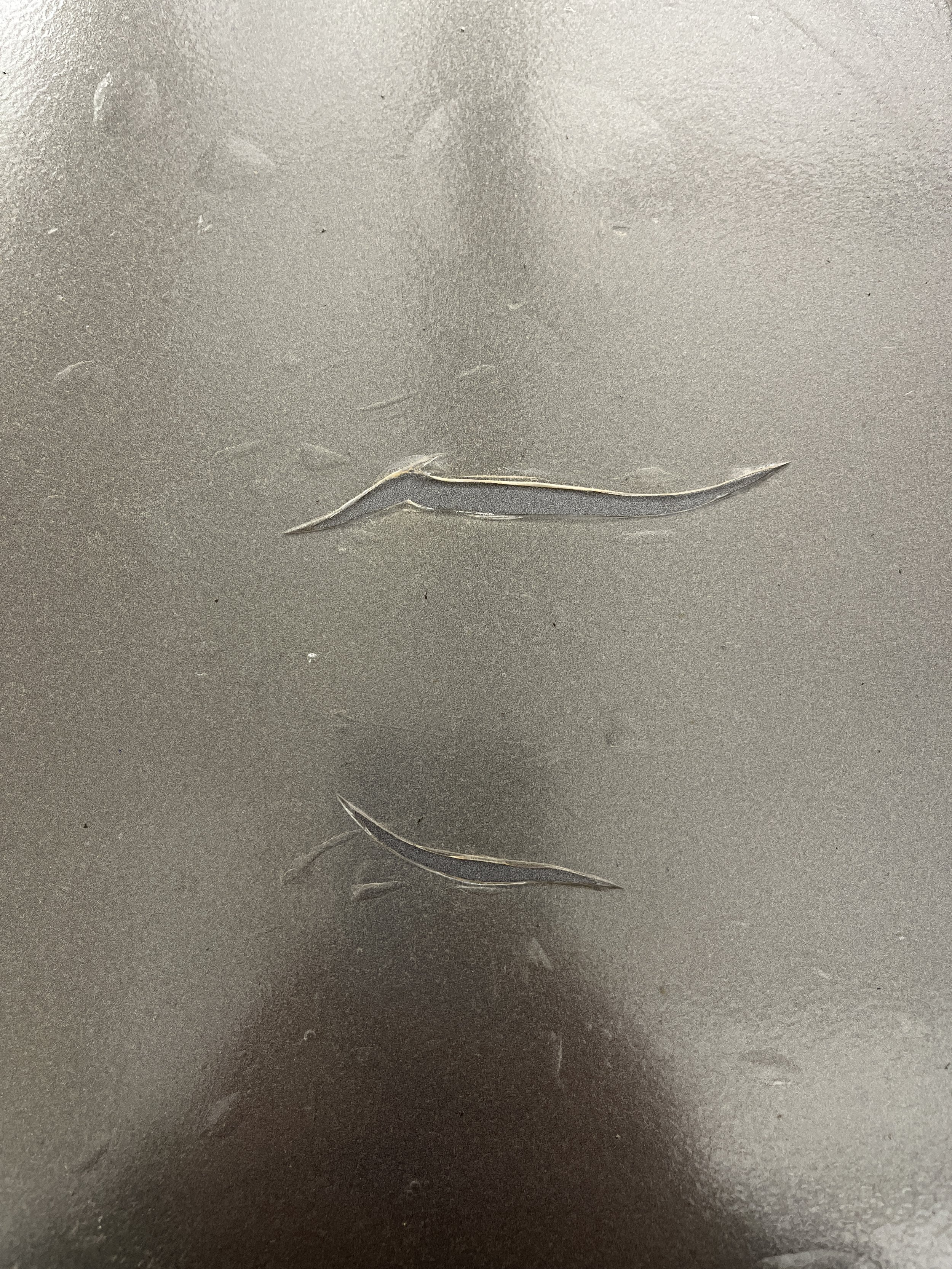
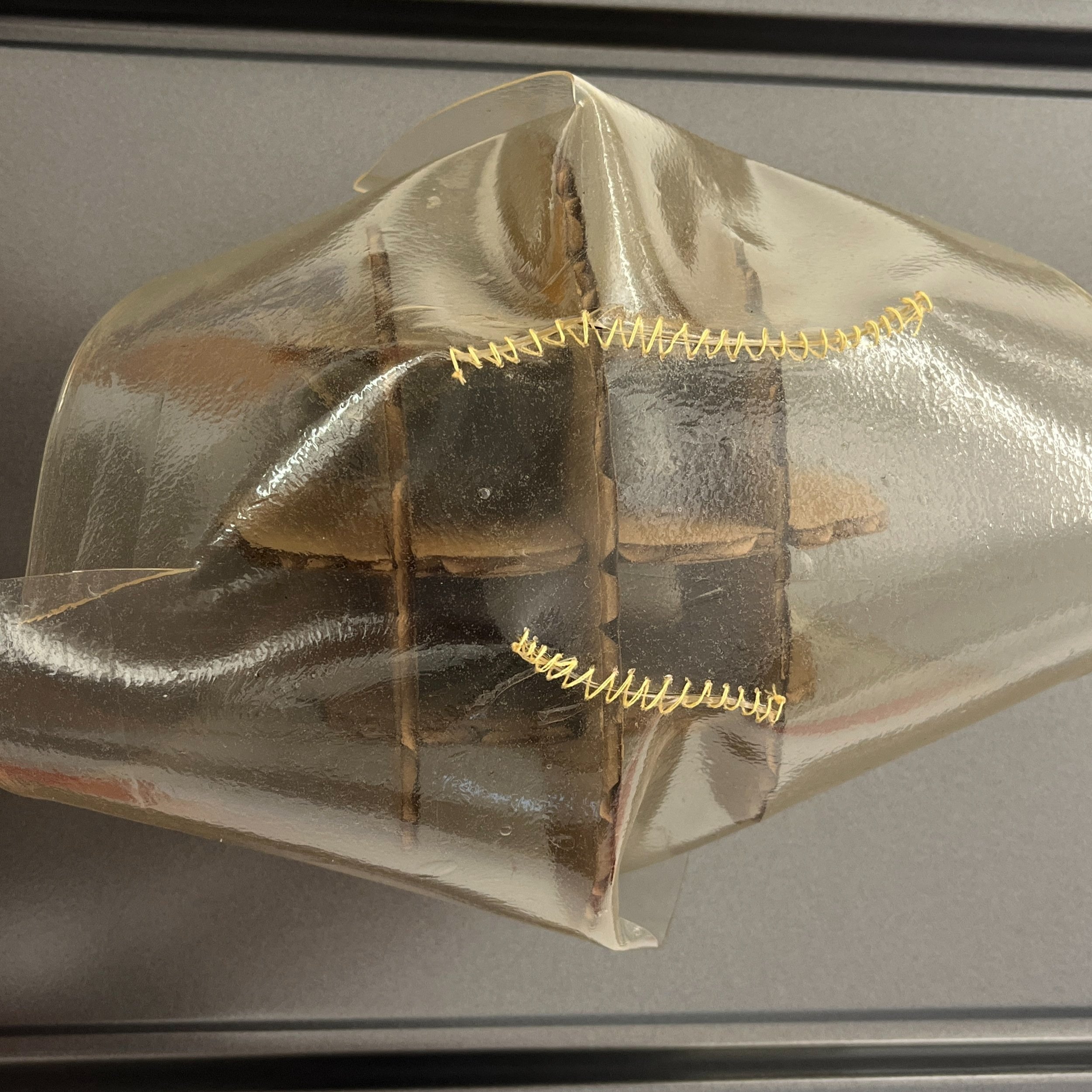
This is the bioplastic ONE WEEK later. It is much thinner and dry to the touch but the rips are much more apparent. I was hoping to mold and bind the sheet around the 3D shape so I mended the sheet with a couple of stitches and tried wrapping the cardboard brain up like a gift. The ribbons are meant to hold the plastic in place and I’m kind of hoping that the bioplastic will just stay in that shape.
PCB v10
If you’ve been following along, you also know that at this point I have two WORKING milled PCB prototypes! Sweet! Now I am moving on to the more final version of the PCB. True to life brain size and many LEDs!
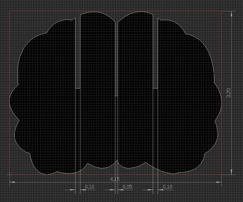
I started with updating my board outlines in Adobe Illustrator. I made sure the slot sizes would fit the PCB thickness and acrylic thickness. To get these outlines into EAGLE, I saved them as SVGs and converted them to DXF files online. However, when I did this, the scale was completely off from the original drawing. The scale is super important to keep accurate because I will have different parts slotting into each other. Turns out there’s a really weird scaling issue going from Illustrator to any other software because they use a different size for pixels than most other softwares. This was super frustrating!!!
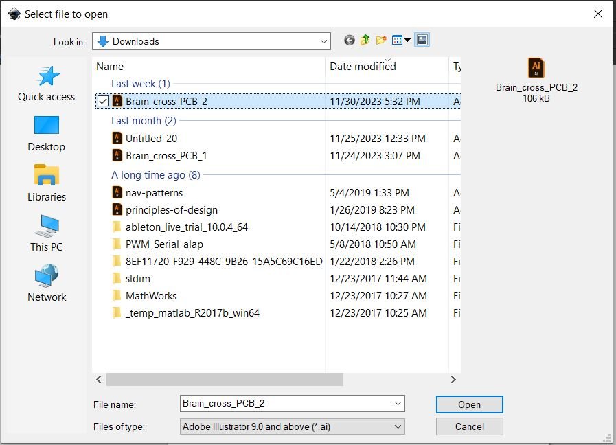
A workaround I found to keep the scaling fixed was to open the original .ai (Adobe Illustrator) files in Inkscape by “File” > “Open” and then being sure to select “*.ai” as the file type. This will take care of properly converting the pixels to the correct size to keep the drawing to scale. I then saved the file as a DXF R12 while in Inkscape and could import the DXF into EAGLE as normal.
Another pro tip is if you place your drawing in the bottom left corner of art board in Illustrator or Inkscape it will align with the EAGLE origin in the board layout on import.
Something else I came across was that the free eagle license has restrictions on board area. I ended up having to switch from my personal login to my school login I created when experimenting with Fusion 360 so that I could access my educational license to create my big sexy brain!
Opening *.ai files in Inkscape
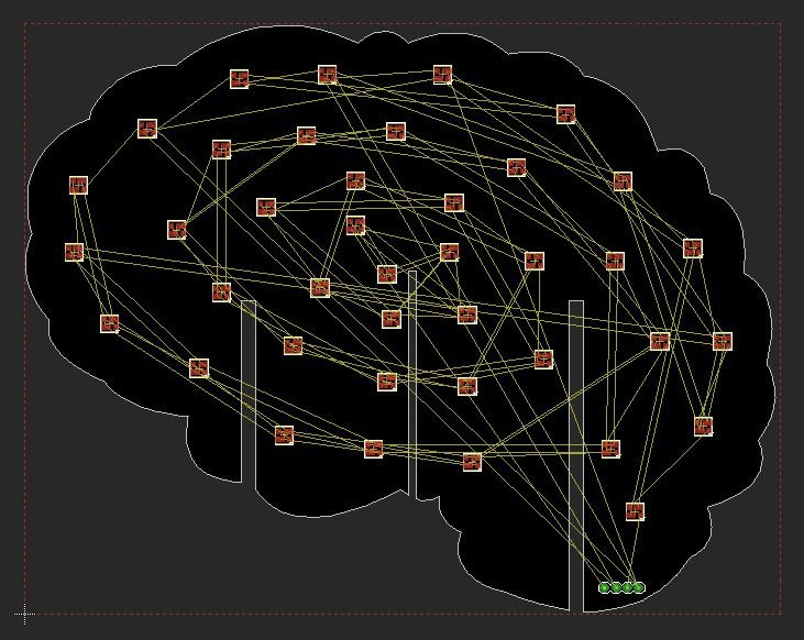
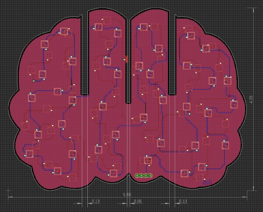
Yay! Here’s the imported PCB shape to correct scale!
This first view of the brain is meant to SPIRAL. I created a schematic with an LED chain 80 LEDs long, 40 LEDs on the top and 40 on the bottom. I first placed all the LEDs, reoriented them so that airwires were shortest, created a 5V plane on the top and a GND plane on the bottom, and then got to routing.
Here are some things I noted while refreshing my memory on using EAGLE:
Command “ripup @ ;” will rip up all polygons so it is easier to see components and airwires
I chose a trace width of 0.01 inch and via drill size of 0.02362205 inch
Ctrl + F flips the board over
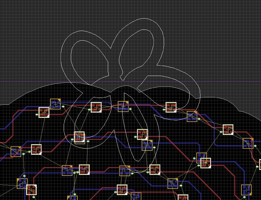
I also attempted importing an Illustrator drawing as a DXF to be on the silkscreen layer and it didn’t quite work. I’d love to be able to draw a bunch of strokes for the fissures of the brain and put those on the white silkscreen layer. On the right is a quick test I did. The stroke I drew translated to an inside and outside outline which is not really what I want. If I could make this only one line, the pen path, then I could potentially draw some folds and bumps to scale, import it like normal, and select all silkscreen and bump up the thickness?
There’s also some nuance between fills and polygons. A fill would be composed of a bunch of lil lines which requires a whole bunch of data but polygons are more SVG-like. I was following tutorials like this but I couldn’t get anything to work. This was too hard for me so I’m abandoning the silkscreen for now.
I shifted gears to the second PCB and I was having the same scaling issues again.
Brain imports too small!
After opening *.ai in Inkscape and saving as DXF, the import is to scale!
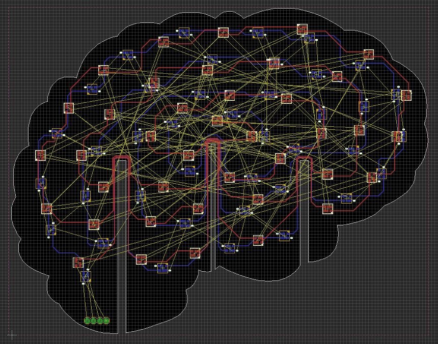
I then went through the same layout and routing process. This brain should look more like normal neurons firing so I laid out the LEDs randomly and will treat it as a graph with neighbors, impulses coming from selected neuron hubs, in software I guess. Hope I can figure that out.
I don’t have any good images, but I also added some extra pads at the slots for the PCB. The idea is that when the two boards are slotted together, I can solder them into place for extra electro-mechanical connection. Not sure if they are the right size. I also grounded them… not sure if that’s right either.
Finished design
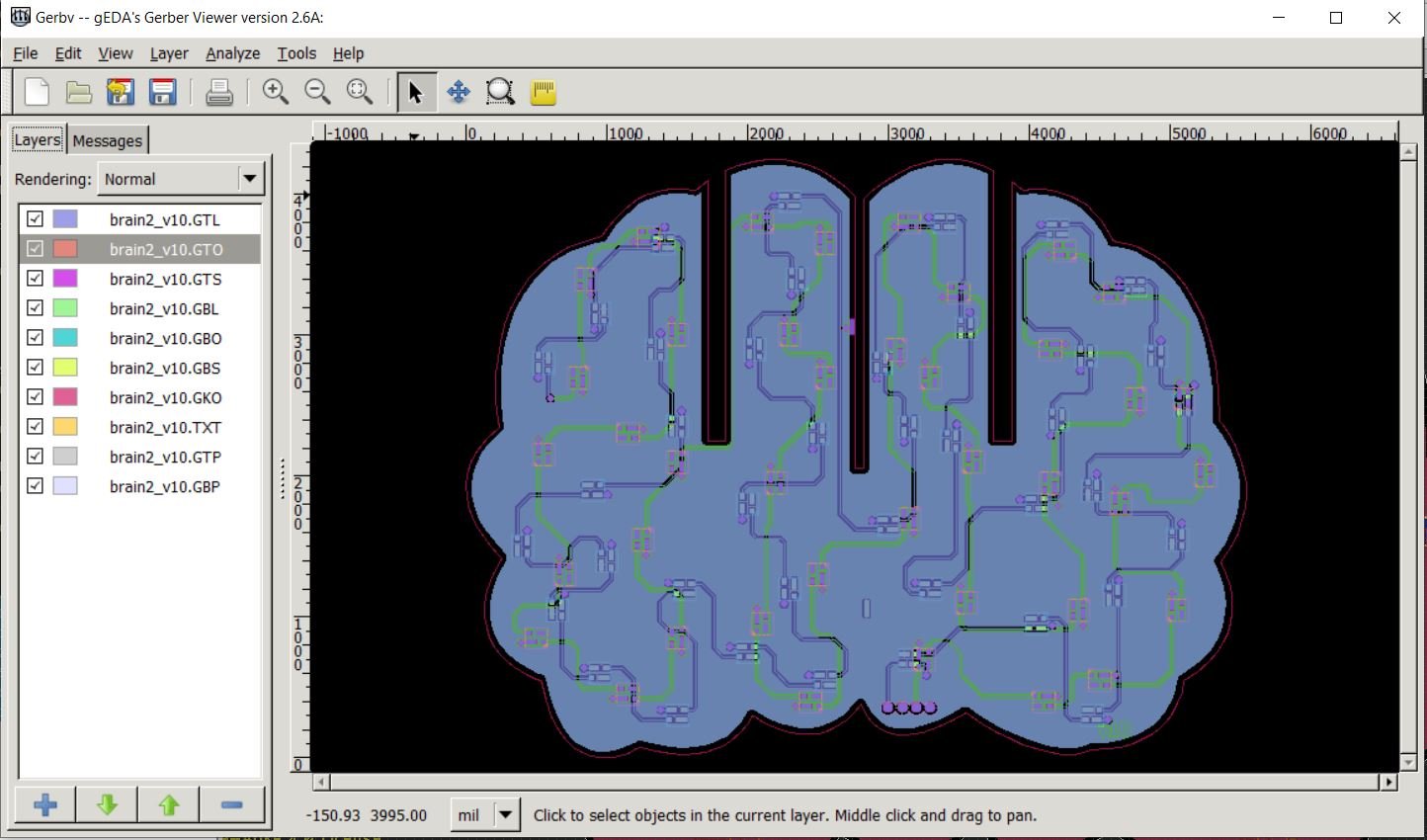
Generating gerbers
Here’s my Github repo with all my EAGLE files.
Design Review with Nick Poole
Time was quickly running out for me, so I had to go ahead and pull the trigger on ordering my v10 of the brain boards but I was able to get some eyes on my design after the fact. I used to work with my friend Nick at SparkFun some years ago now. Luckily, he’s the best person ever and responded to an email from a desperate graduate student and estranged co-worker. He was able to look over my design and give me pointers on creating 3D PCBs. In fact, he’s an expert on Boggling the Boardhouse and even gave a whole presentation at SuperCon some years ago. I’m really so lucky to know such smart and kind people and am excited to take Nick’s pointers and develop brain boards v11 soon!
References
Adobe Illustrator scaling issue in Inkscape
Inkscape scaling issue with SVG files (this didn’t end up fixing my issue but is still relevant)
Importing custom images into EAGLE

