
Overview
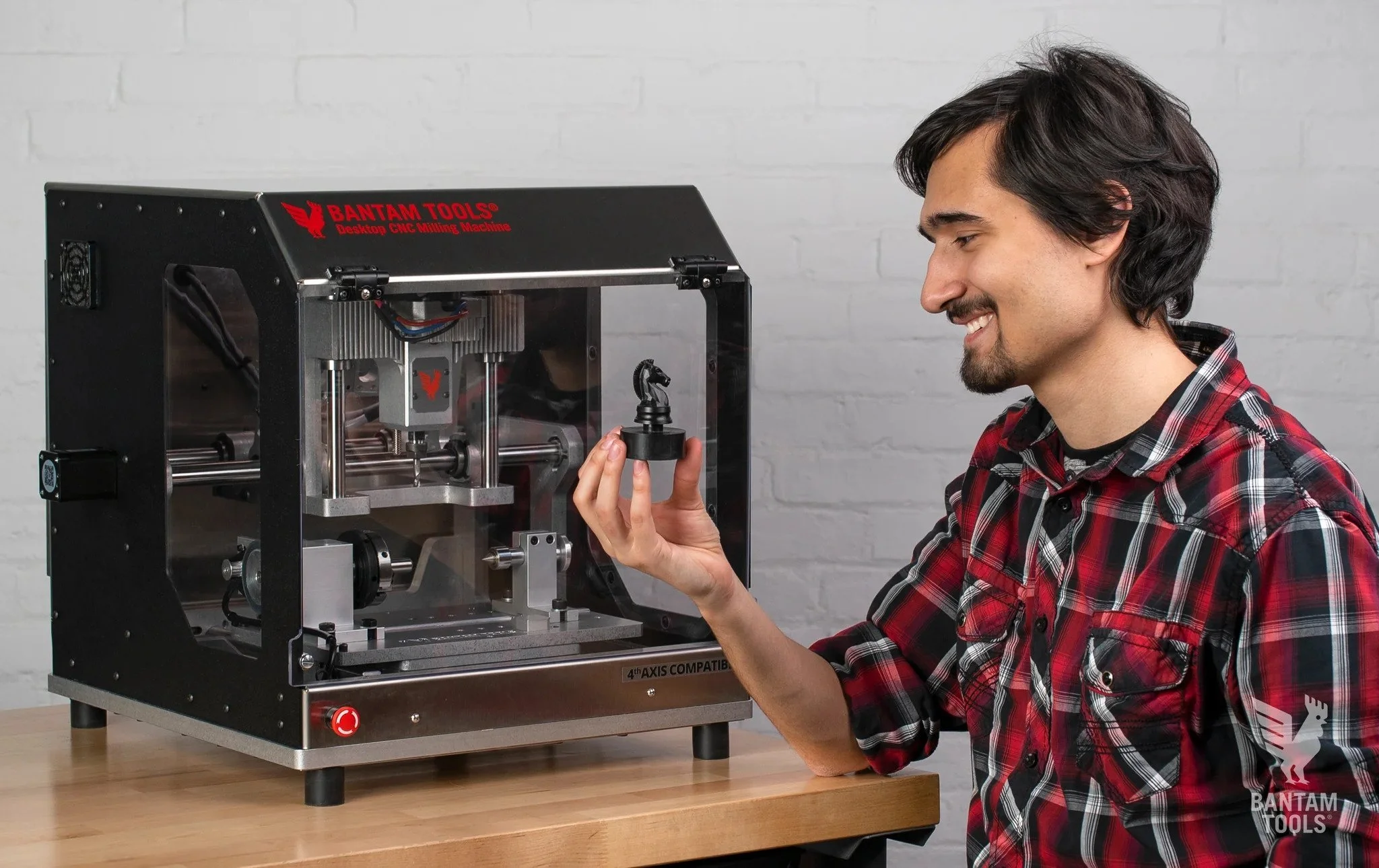
The Bantam Othermill is a Desktop PCB milling machine. It is for milling printed circuit boards, small 3D parts, and engraving. A milling machine removes material from a work piece by rotating a cutting tool and moving it into the work piece.
There is also a fourth axis attachment with which you can rotate a material around the x-axis and mill away material to make 3D parts.
Working Volume
The milling area is pretty small: 4.5 x 5.5 x 1.35 inches with spoilboard installed and 4.5 x 5.5 x 1.6 inches without. There are no spoilboards installed on the mills in the shop and Phil said there was a little more wiggle room with the material thickness, more like 2 inches max.
Materials
Don’t use these:
Steel (stainless or otherwise)
Iron
Titanium
Fiberglass
Hard stone and precious gems
Glass
Food products
Use these:
FR-1 PCB blanks
Machining wax
Linoleum
ABS
Acrylic
Brass (for engraving)
Aluminum (for engraving)
Silver (for engraving)
For a complete list of materials you can use and tips, check out this article.
Confusion between Othermill and Bantam Desktop CNC
Othermill and Othermill Pro are both small table-top CNC mills from Bantam. They can be identified by their white plastic housing and we have many of them in the ITP shop. Bantam stopped selling them in 2017 and Phil was adamant in focusing on the Desktop machine (still being manufactured/supported) with its wider capabilities.

Othermill

Bantam Tools Desktop PCB Milling Machine

Before you begin - what you need
Design file - SVG, BRD, Gerbers, and G-code files
Milling material - cuts most any material softer than steel, for example wood, plastic, machining wax.
Milling tool - 1/32” Flat End Mill and 1/64” Flat End Mill are included, but you can use any cutting tool that has 1/8” shank. We have all the tools, bits, and things in the shop. Eventually there will be kits available for check out in the shop.


Software
You can download the Bantam Tools Desktop Milling Machine Software from here but there are computers in the shop designated for use with the Bantam machines with the software already downloaded. All you need is your design file on a flash drive.
Other softwares that might be handy are ones used for drawing and/or modeling like Fusion360, EAGLE, Inkscape, etc. The software is expecting .svg, .brd, PCB Gerbers, or G-code files. Some CAM software requires a Bantam Tools post-processor to allow for integration with the milling machine. The post-processing software translates the mill design into tool paths and machine movements specific to the Bantam.
Process - Cutting sample PCB
Checkout a Bantam tool set kit from the ITP shop. Below are some of the things you might use when working with the Bantam. There’s also a drawer under the work bench with a bunch of tools and materials for working with the mill.


2. Plug desktop mill into power and make sure the computer is connected to the machine over USB.
3. Turn on the machine with the switch in the back. When it is first powered on, the mill will calibrate itself.
4. Open your design file in the Bantam 2.0 software. The software will prompt you through the setup and milling process. In the screen shot below you can see that there’s a warning. As a safety feature, the mill won’t rotate if the front door is open.
5. Start by installing the tool you will be using. The machine should be left in a state where no tools or bits are installed. If there’s any hardware already installed, feel free to remove it. For our setup, we installed the fan on the bit to remove excess material. Screw the collet into the nut and the bit into the collet. Use the two wrenches to install the tool but make sure to keep it only finger tight so it can be removed in the future.


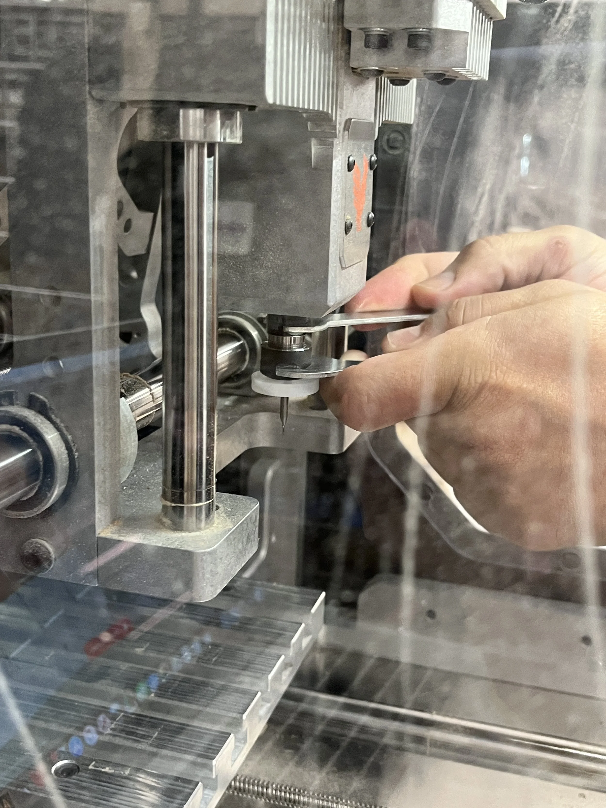

6. The software will prompt you to go through the process of locating the newly installed tool. The machine will go through an automated process of conductively measuring the vertical distance between the tool tip and the collet so that the machine knows where the tip of the tool is in space.
7. Follow the software prompts to define the material and size. Make sure to double-check all these measurements.
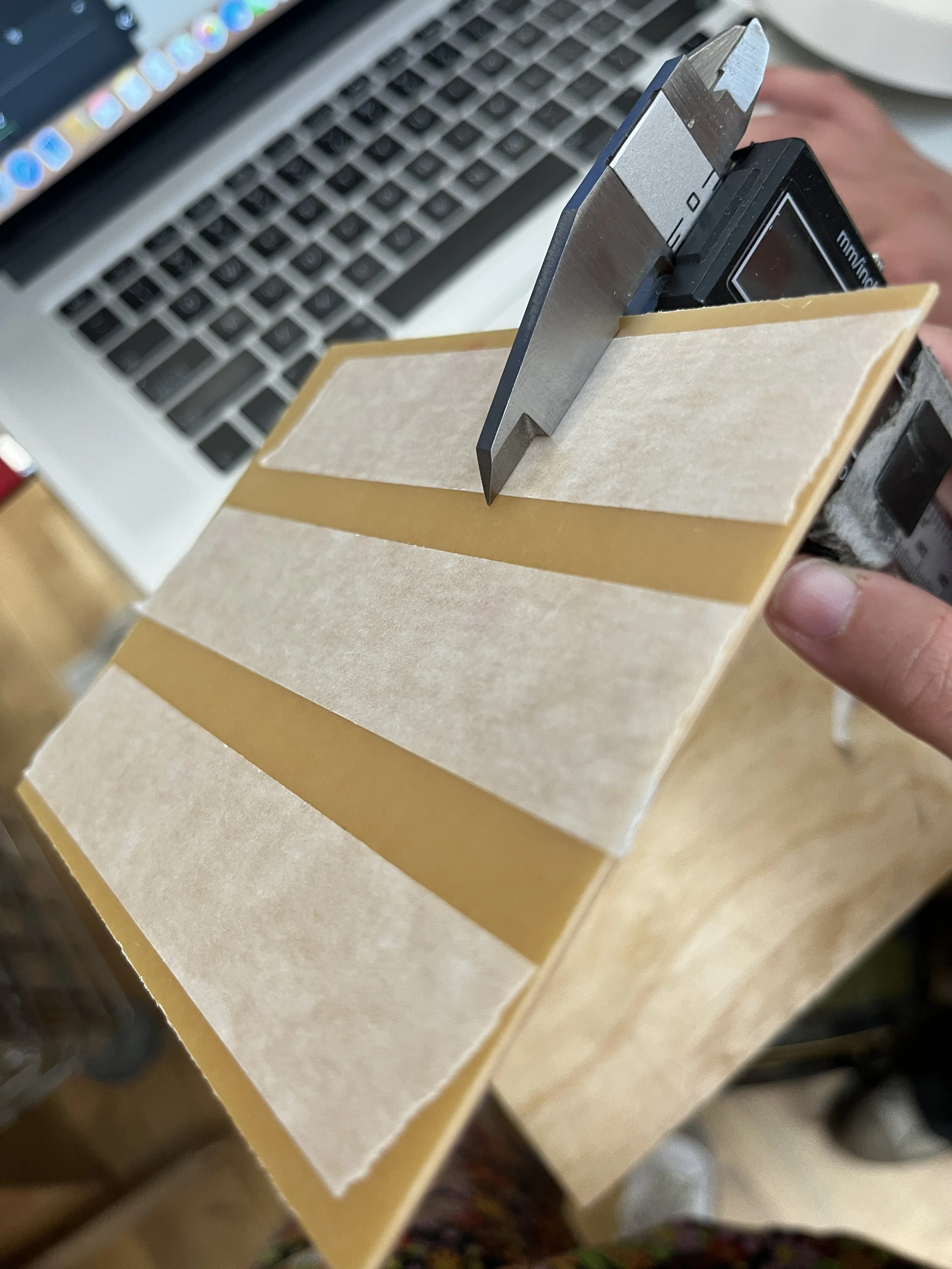
8. Prep the material for install. The sheet of FR-4 will be stuck down to the bed using double-sided tape. Make sure to cover as much as the area as possible being careful to not wrinkle or double up on tape. Inconsistencies in material level will affect the cut. At some point the software will ask for z-offset so make sure to measure the PCB material with the tape, both sides of paper backing removed.


9. The software will prompt you to attach the material and push the bed forward. You can clean the bed down with rubbing alcohol. Place the material as close and lined up to the bottom left corner as possible. This is the origin. Stick the material down.
10. Confirm the placement and scale of your design and tool path. Be sure that what you’re milling was designed with the tool in mind and never place your design directly on the edge of the material.
11. Setup is complete, now we can run the mill! NOTE: the Bantam laptop isn’t currently logged into the PCB subscription needed to cut the .brd file but the shop is working on getting laptops setup for checkout with all the correct softwares and subscriptions for any digi-fab process.

Voila!

12. The last thing to do is remove the circuit board from the bed. Use the scraper to gently pry the material. You can use some isopropyl to try to loosen the adhesive. Remove all bits from the machine and put everything away.
Notes
Lines can only be milled if they are as wide as the width of your tool
Remember, the smaller the tool, the more fragile it will be and the slower you’ll need to cut. Big tools are great for roughing passes and clearing out lots of material.
The tool moves in the z- and x-direction, the bed moves in y-direction

Terms
CNC = computer numerical control, all of the robot-y machines in the shop are CNC’s
CAD = computer-aided design. Softwares include: SolidWorks, Fusion360, VectorWorks, etc
CAM = computer-aided manufacturing
Collet = a segmented band or sleeve put around a shaft or spindle and tightened to grip it

Shank = the end of a drill bit grasped by the chuck of the drill
Spoilboard = disposable workbench mounted above a working/milling surface
Fixturing = the process of secuting the material to the milling machine’s bed
For my own reference…
FR = flame retardant materials
FR1 = paper substrates for single-sided boards, ROHS certified
FR2 = basically FR1
FR3 = basically FR2, except it uses epoxy resin instead of phenolic resin
FR4 = glass fiber composite with a flame retardant epoxy resin, water resistant, superior electrical insulation, excellent copper adhesion, preferred for multi-layer PCBs
Resources
Bantam Tools Desktop PCB Milling Machine Documentation
Bantam Tools Milling Machine Software